
How to Diagnose Faulty Electric Brakes
This article will outline the basic steps to diagnose an electrical fault with the electric trailer brakes.
Possible Faults
1. The ground wire is touching the Blue (brake wire) this could happen inside the 7-pin plug.
2. One of the brake magnets might have grounded (unplug one by one to see if the fault goes away).
3. The Rock Guard bolt may have pinched the chassis wiring loom and caused the blue wire to ground to the chassis.
4. The tow vehicle wiring mat be faulty.
If the fault only occurs when the brake away switch is activated and not when the tow vehicle brakes are applied, then the fault is likely with the brake away switches, it could have shorted to the ground.
How to Locate a Brake Wiring Fault
Open the 7-way plug and check for wiring short.
Disconnect the 6-way plug between the chassis and the tongue/drawbar to see if the fault goes away, this effectively isolates the fault to either the drawbar wiring or the chassis wiring.
If the short is in the chassis side of the wiring then disconnect each brake hub at the hub one at a time to see if the fault goes away.
If all brake hubs are disconnected and there is still a direct short from the blue wire to earth then a Rock Guard mounting bolt may have pinched the chassis wiring loom and caused the blue wire to ground to the chassis. Prize back the cover plate and visually inspect the wiring loom for damage.
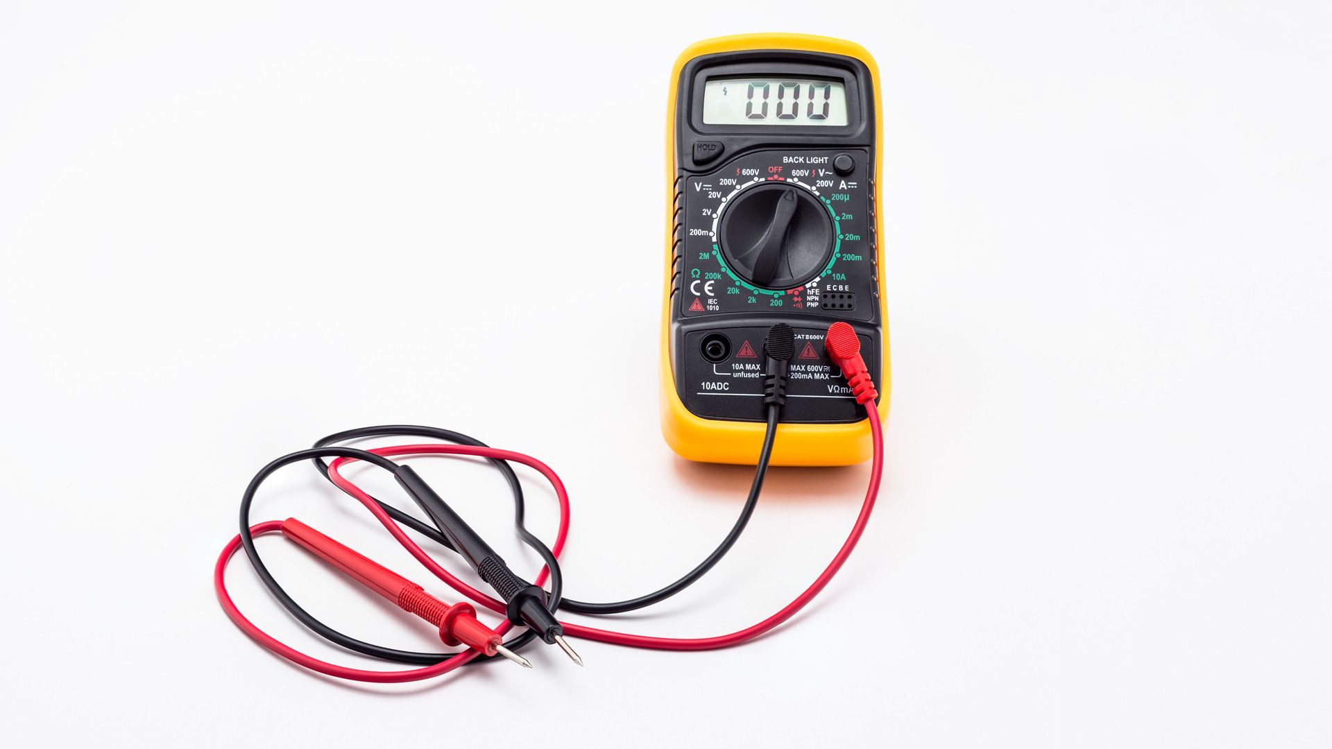
How to Test the Brake with a Multimeter
To test trailer brakes, set your multimeter to Ohms, place the negative probe on one of the brake magnet wires, and place the positive probe on the other magnet wire.
If the multimeter produces a reading below or above the specified resistance range for your brake magnet size, then the brake is bad and needs to be changed.
This process is only one method of testing individual brakes and these steps, as well as other methods, will be explained further.
There are three ways of testing your brakes for problems:
- Testing resistance between brake wires
- Testing amperage from the brake magnet
- Testing current from the electric brake controller
Testing the Resistance Between Brake Magnet Wires
1. Set Multimeter To The Ohms Setting
To measure resistance, you set your multimeter to Ohms, which is usually represented by the Omega symbol (Ω).
2. Position Multimeter Probes
There is no polarity between your brake magnet wires, so you can place your probes anywhere you want.
Place your black probe on any of the brake magnet wires and place the red probe on the other wire. Check for readings on your multimeter
3.Evaluate Results
With this test, there are certain specifications you want to note down.
For a 10-inch brake drum, you expect a reading between 3.8 – 4.0 ohms.
If the reading you get from your multimeter is outside these ranges as they relate to your brake drum size, then the magnet is bad and needs to be replaced.
For instance, the multimeter presenting "O.L" indicates that there’s a short in one of the wires and the magnet probably needs to be changed.
Testing Amperage From Brake Magnet
1. Set Multimeter To Measure Ampere
The first step is to put your multimeter on the ammeter setting. Here, you want to measure if there’s any internal exposure or breaks in the wires
2. Position Multimeter Probes
Pay attention to these positions. Place the negative probe on any of your wires and place the positive probe on the positive terminal of your battery.
You then place the brake magnet on the negative battery post.
3.Evaluating Results
If you get any ampere reading from the multimeter, then there is an internal short in your brake magnet and it needs to be replaced.
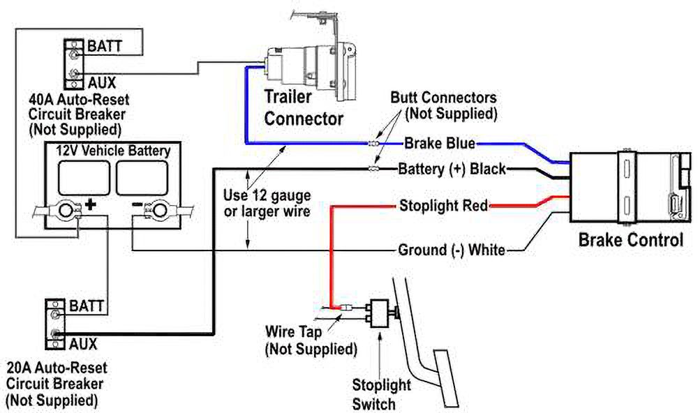
Testing Current From The Electric Brake Controller (Tow Vehicle)
Electric brakes are managed by an electric brake control panel.
This panel feeds the magnets with an electric current when the brake pedal is pressed, and your vehicle stops.
Now, a problem with your brakes arises if this electric brake controller isn’t working properly or the current from it isn’t adequately reaching your brake’s electromagnets.
To test this device, there are four methods.
You can use a multimeter to test the trailer brake wiring between your brake controller and the brake magnet.
When generally testing brakes for problems, you want to take note of certain things.
These are the number of brakes you have, your trailer pin plug configuration, and the recommended current the magnet wires are meant to produce.
This recommended current is based on the size of the magnet, and here are the specifications to follow.
For Brake Drum Of 10″ – 12″ Diameter
- Trailers with 2 brakes: 7.5 – 8.2 Amps
- Trailers with 4 brakes: 15.0 – 16.3 Amps
Now, follow these steps:
1. Set Multimeter To Measure Ampere
Set your multimeter dial to the ammeter settings
2. Position Multimeter Probes
Connect one probe to the blue wire coming from your connector plug and the other probe to one of your brake magnet wires
3. Take Reading
With your car powered on, activate the brakes through the pedal or electric control panel (you can have a friend do this for you). Here, you want to measure the amount of current coming from the connector to the brake wires.
4. Evaluate Results
Using the specifications mentioned above, determine whether you are getting the right amount of current or not.
If the current goes above or below your recommended specification, then the controller or wires may be bad and need to be changed
There are also other tests you could run to diagnose the current coming from your electric brake controller. Consult a qualified automotive electrician.
Other Resources
Loading articles